
Abstract: This paper introduces the design of a computer monitoring system for the successful application of magnetron sputtering coating production line. It focuses on the hardware configuration, software design, communication protocol, control process implementation and software programming control algorithm of computer monitoring system.
DJW (L) series horizontal (vertical) magnetron sputtering coating production line produced by Zhaoqing Dali Vacuum Equipment Co., Ltd. uses DC power source or medium frequency power supply control plane target, cylindrical rotating target or intermediate frequency twin target to sputter film on the workpiece. It is widely used in various architectural glass, ITO transparent conductive glass, home appliance glass, high reflection rearview mirror and acrylic coating.
Tsinghua Microelectronics has introduced high-frequency tube discrete device die, which has achieved 9G cut-off frequency. This series of production lines combines the unique technology and user-friendly design concept while absorbing the advanced technology and coating process of similar production lines in Europe. The user community has been fully affirmed.
In this series of magnetron sputtering coating production lines, a 10.4 inch pro-face color touch screen has become the standard operation interface as the main operation interface, and the work is also stable. Due to the need to control more process parameters in the coating production, in order to improve The work efficiency and the controllability of the coating process, we designed a computer monitoring system to complete the monitoring and parameter optimization of the entire production process, so that the coating production has a good process repeatability, more suitable for work
The need for industrialized mass production.
1 Functional design of the monitoring system
The computer monitoring system is designed to have the following functions according to the working conditions of the production line and production requirements.
(1) Mode selection: In order to meet the working needs of the production line, the computer monitoring system is designed with two operating modes: an automatic monitoring mode for coating production and a manual monitoring mode for debugging and maintenance. The two operating modes are free. Switch.
(2) Process plan selection: In order to realize the coating automation of various workpieces, the monitoring system has designed a variety of process plans for the user to choose, select the solution to be used before the equipment is running, or set a new plan by itself, and then start Coating production.
(3) Data detection record: In order to facilitate the user to monitor the process, analyze the role of process parameters, and adjust the process parameters in time to obtain better coating effect. The monitoring system: 1) display the voltage and current of each magnetron target in real time. Each vacuum count value, gas flow and other parameter values; 2) Timing recording equipment operation, recorded every 30 minutes, or recorded as required; 3) Record important process parameters, and form report files and historical curves.
(4) Fault alarm record: 1) When the equipment fails, the monitoring system automatically pops up the alarm screen and text prompt, and the alarm light flashes; 2) Record all alarm information for inspection during maintenance; 3) According to the priority of the fault, Classify alarm information.
(5) Automatic diagnosis protection: This is a kind of protection measure to reduce damage caused to the equipment due to failure. The main performances are as follows: 1) When the equipment has serious failure, the monitoring system can automatically shut down; 2) After the magnetic control power is turned on, The voltage and current are ramped up and down to protect the power supply; 3) It is possible to detect whether the communication between the upper and lower computers is normal.
(6) Operation authority limitation: This function can be used to limit the permissions of general users, prevent misuse and reduce the probability of error; at the same time, it can realize the unification of control and monitoring.
(7) Other functions: The computer monitoring system also sets some useful functions such as system clock, device input and output point monitoring interface, device operation description interface, etc., which are convenient for users to query and use.
2 The composition of the monitoring system The computer monitoring system consists of the upper computer, the lower computer and the communication protocol. The hardware structure of the system is shown in Figure 1.
The upper computer is used to monitor the production operation status and production process data, complete the complete control of the coating production, and take the historical data obtained as a proof of the coating effect detection analysis. Because the environment interference of the host computer is small, the ordinary PC is selected, and the operating system adopts Microsoft Windows XP with good versatility and strong function. The monitoring and data acquisition software uses the easy-to-control (INSPEC) E20 universal configuration monitoring system software developed by Beijing Jiu Siyi Automation Software Co., Ltd. It is the world's first similar product based on Microsoft's latest operating platform .NET, with powerful monitoring functions. It has a series of advantages such as stable performance, exquisite graphics, easy to learn and use, high efficiency and easy expansion. It uses high-level language C# as the user program (script) language, which can meet the control requirements. The functions of acquisition and data display are also perfect. As long as the driver of the device is installed, it can communicate with various PLCs, smart meters, boards and inverters, and can also be connected with other computers to form a distributed enterprise. Production management network.
The application of the easy-to-control (INSPEC) universal configuration monitoring system software develops the automatic control screen, and the coating production can be monitored in real time through the upper computer screen, and the important data is recorded in the file. When abnormal production occurs, the over-limit or fault sound alarm and text prompts are displayed, and the relevant screen is popped up, which is convenient for the operator to quickly analyze and process, so as to resume production in the shortest time.
The lower computer consists of Mitsubishi PLC plus various modules, including: one FX2N-128MR host, one FX2N-16EYR output expansion module, four FX2N-4DA analog output modules, two FX2N-4AD analog input modules one FX2N-232 - BD communication board.
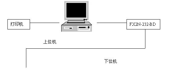

The easy-to-control (INSPEC) universal configuration monitoring system supports OPC server and can be connected to third-party software: Since Mitsubishi PLC has a special communication driver, serial RS-232 shielded cable is used between the upper computer and the lower computer for data exchange. The data communication between the upper computer and the lower computer is carried out in question and answer mode. The communication command (downlink command) is sent by the upper computer to the lower computer. After receiving the corresponding answer command (uplink command) sent back by the lower computer, the upper computer continues to send the downlink. The form of communication for the command. According to the requirements of the monitoring system function, the communication protocol is transmitted by using the periodic command mode, and the data transmission adopts an event-driven communication mode. For the received data communication, the communication protocol is sent to the upper computer after performing frame length check, character check and timeout check. If an error is found during verification, the retransmission mechanism is applied to retransmit the error frame until it is correctly received.
All control work is done by the lower computer. The upper computer is only responsible for providing human-computer interaction interface, command receiving and sending, automatic process control, data display storage, parameter setting, report printing and data processing. During the operation of the system, the upper computer communicates with the lower computer in real time, so that the data displayed on the interface is consistent with the actual data; the operation commands and set parameters sent by the operator on the upper computer can also be sent to the lower position in real time. Executed on board. Thanks to the touch as a redundant operating device, the production line can be switched from the computer monitoring system to the touch screen operation mode at any time without affecting production, facilitating equipment maintenance and improving system reliability.
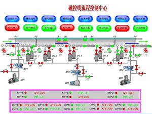
3 system process design control process realization <br> according to magnetron sputtering coating production line
The second process is ion bombardment. In order to improve the adhesion of the film layer, high-energy ion bombardment is used to clean the surface of the workpiece to remove surface debris and dirt.
The third process is magnetron sputtering coating. The electrons emerging from the cathode are subjected to Lorentz force in the magnetic field and electric field, and the cycloid force is advanced along the direction of the magnetic field, and deposited on the surface of the workpiece to form a thin film. ;
The fourth process is the system switch machine, which is the processing operation of the entire equipment before and after coating.
3.1 The automatic control of the vacuum acquisition process The vacuum system of the magnetic control coating production line uses a slide valve vacuum pump, a Roots vacuum pump, a high vacuum oil diffusion pump unit to obtain low vacuum and high vacuum, and a microcomputer-based digital vacuum gauge to detect the vacuum. Degree, the automatic control of the process includes: 1 mechanical pump, diffusion pump, vacuum gauge, start and stop control of the pump; 2 high and low vacuum value output control of each vacuum gauge; 3 opening and closing control of each vacuum valve and flap valve .
The entire unit is cooled by circulating water, so the system cannot turn on the vacuum unit until it receives the water pressure indication. The flap valve is used to isolate the atmosphere from the low vacuum chamber and between the low vacuum chamber and the high vacuum chamber; the vacuum valve is used to control the on and off of the vacuum pumping passage. The system opens and closes the valve by controlling the pneumatics.
3.2 Automated control design of ion bombardment process For some models (such as acrylic coating production line), in order to improve the adhesion of the film, the system uses high-energy ion bombardment as a pre-plating treatment process. In the bombardment cleaning process, the control indicators are argon mass flow, bombardment voltage, bombardment current, bombardment time and transmission speed; in order to meet the requirements of the coating process, the workpiece can be slowly passed through the bombardment chamber while bombarding while traveling; The workpiece is selected to stay in the bombardment chamber, and after a period of bombardment, it enters the buffer chamber, which achieves high-energy ion cleaning of the workpiece.
3.3 Automatic control system design of coating process In order to meet the requirements of coating process, it is necessary to control the argon mass flow rate, reaction gas mass flow rate, sputtering pressure of each target, sputtering current and coating speed of coating. Before the workpiece travels to the magnetron target, the target current is automatically transferred from the maintenance state to the working state, and the workpiece is coated until the workpiece leaves the target, and then returns to the maintenance state, thereby maximally saving the target.
In order to effectively protect the magnetron target and the target power supply, the system has designed the water pressure, vacuum degree control and overcurrent, overheat fault alarm function, as well as the slow lifting function of the target power supply voltage and current.
3.4 The automatic control design of the system switch machine is automatically started. It starts from the preheating of the diffusion pump. The vacuum pumping system works automatically until the vacuum degree of the coating chamber is reached. The magnetron target is automatically started. All the operations of this process are performed by the equipment. automatic completion.
The automatic shutdown is to automatically close the magnetic control target after the production line coating work is completed, and gradually close the vacuum pumping system. All operations in this process are automatically completed by the equipment.
4 Algorithm Control 4.1 Feedback Algorithm In the application process of the system, there is always a certain error between the set value and the display value of the magnetron power supply. In order to achieve the unity of the two, our application software designs a feedback algorithm for the power supply. The data setting and display are very effective.
Set the current power display data (acquisition data) to X n. After the time T, the display data is X n+1, the initial setting value of the power supply is S1, and the modified setting value is S2. The specific calculation flow is shown in Figure 2.

d, k, and e in the flowchart are the selected constants. _X n+1-X n _
4.2 Range Conversion Algorithm The whole set of monitoring system range conversion is divided into two parts, three stages.
Part 1: Data Display:
1) The power supply range is converted to 0~10V output 2) 0~10V output is converted into 0~2000 integer input to computer 3) 0~2000 integer is converted into power supply range for display. Part II: Data setting 1) Power supply The range is converted into 0~500 integer output computer 2) 0~500 integer conversion to 0~10V input power supply 3) 0~10V input is converted into power supply quantity program to set each stage of conversion is a linear simulation process, It is only necessary to calculate the conversion slope to find the corresponding conversion value. For example, the 0~10V output is converted to 0~2000 integer, and its conversion slope is K=2000/10=200. For any input X, the conversion value Y= KX=200X
5 Conclusion <br> The computer monitoring system of the magnetron sputtering coating production line introduced in this paper has been operated and used, with stable operation and reliable performance. The picture is vivid and expressive, with better monitoring effect and improved user system image. As a successful coating production line computer monitoring system, we plan to use it to a variety of coating equipment, so it has great promotion value and application prospects, thus promoting the development of computer monitoring technology for vacuum coating equipment in China.
:
New generation full automatic Flap Disc machine adopts brand new design concept,many parts were optimized compared with former generation,the whole structure is more precise and more stable, thus flap disc stability and durability is effectively improved. full automatic flap disc machine can automatically upload backing,detect backing,quantitatively feeding,flap cutting and setting, shaping and automatically download finished flap discs with high automation. Flap disc quality is very good and under control.
Main Features
A. Head System
â‘ Using lift model to ensure that the product defect rate less than 1%~2%
â‘¡ Using Head tilt operation to finish T29 type producing
â‘¢ When converting different types of products can be achieved quickly adjusted conversion.
â‘£ Muted effect,low noise and vibration,excellent durability,the worker operation improved,environment has been greatly improved.
⑤ An inspection system to prevent an erroneous operation.
â‘¥ High utilization of emery cloth strips.
B. Turntable System
Each Pallet smooth transition fast, precise positioning,good durability.
C. Gluing System
â‘ Smart thermostat water circulation system.For adhesive road achieve comprehensive heating.In order to get better performance of the glue,ensure the stability of setting abrasive sheets.
â‘¡ Gluing system with the last design,ensure accuracy of the glue volume,consistency and durability,the stability of product quality is guaranteed.
D. Convey Machine
All intelligent automatic feeding,feed off,abrasive cloth roll can be change quickly and easily.
The related abrasive products we can supply is Flap Disc Adhesive , Bonded Abrasives ( Cutting Wheels and Grinding Wheels ), Abrasive Sanding Disc, Flap Disc Backing Pad and Abrasive Flap Disc, if you have any needs about abrasive tools, please kindly feel free to contact us.


flap disc machine,Flap Disc Making Machine,flap wheel machine,Flap Disc Make Machine,Flap Disc Forming Machine
Zhengzhou Jiading Abrasive Manufacturing Co.,Ltd , https://www.jiadingabrasive.com