
1. Numerical control transformation of horizontal lathe
The numerical control transformation is carried out on the CA6140 horizontal lathe (or the numerical control lathe can be used with horizontal two-axis linkage), see the attached drawings. Lathe horizontal ball screw 7 pitch P=5 mm, lathe lateral (X-direction) stepper motor 8 running control accuracy is 0.005mm; lathe longitudinal ball screw 9 pitch P=12 mm, lathe longitudinal (Z-direction) stepping The operation control accuracy of the motor 10 is 0.005 mm; the two motions are controlled by an economical numerical control system with two axes linkage (this part can also utilize the original numerically controlled lathe). The difference from the horizontal CNC lathe is that the original lathe tool holder (or electric tool holder) is replaced with a small power milling head 6 for holding various types of shank (rod) milling cutters 5, the spindle axis of the power milling head. It is perpendicular to the centerline of the lathe (it can also be rotated 90° parallel to the centerline of the lathe). The power milling head is controlled by a separate motor. Replacing the power milling head with a lathe tool holder (or electric tool holder) restores the structure of the CNC lathe. The longitudinal (Z-direction) of the lathe and the lateral (X-direction) movement of the lathe are controlled by a two-axis CNC main system.
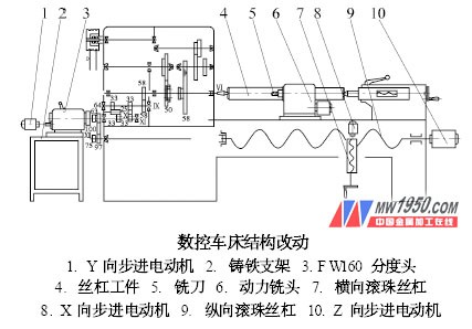
In the left end of the XI axis of the CA6140 lathe headstock, see the attached drawing. Remove the gear (z=100) connecting the XI axis and XII axis in the original lathe, connect the left end of the XI axis with the F W160 universal indexing head 3, and select another stepping motor (the same technical parameters as the X-direction stepping motor). , P=5 mm, the displacement control accuracy is 0.005mm. For the sake of difference, it is set as the Y-direction stepping motor). It is used to connect the input worm of the F W160 universal indexing head. Therefore, the lathe spindle VI can be realized. 4) Rotation control (this should first make the lathe spindle in the neutral position). The F W160 universal indexing head and the Y-direction stepping motor are mounted on the cast iron bracket 2. Remove the cast iron bracket and install the gear of z=100 to restore the transmission connection between the original headstock of the horizontal lathe and the feed motion. The rotary motion of the workpiece is controlled by another set of two-axis linkages (which can be used with other CNC lathes). The CNC subsystem is controlled by the command of the CNC main system. The two sets of CNC systems are preferably identical to facilitate simultaneous programming and CNC machining.
Next page
Ratchet Tie Down,Ratchet Straps,Small Ratchet Straps,Best Ratchet Straps
Jiangsu Zhongyi Work Rigging Co., Ltd. , https://www.zy-rigging.com