
- The production of machine parts is often done through processes such as blank manufacturing, cutting, and heat treatment. The heat treatment process is arranged to facilitate molding, and some to eliminate defects in other processing steps, such as forging defects, and to improve machine performance. Therefore, the heat treatment process according to the purpose can be arranged before, in the middle or at the end of other processing processes. The quality of the heat treatment process can affect the quality of other processing processes, while other processing techniques can also affect the quality of heat treatment and even cause heat treatment waste. Whether the arrangement of the heat treatment process and other processing steps is reasonable, and directly affects the quality of parts processing and heat treatment.Effect of forging process on heat treatment quality
1. The effect of forging heating
Forging heating temperatures are generally as high as 1150 ~ 1200 ° C, often with overheating defects after forging. This overheating defect is difficult to eliminate by the normal normalizing method due to the intragranular texture. Therefore, in the final heat treatment, the grain size of the quenched structure tends to be coarse, and the impact toughness is lowered. During chemical heat treatment, such as carburizing or high-temperature carbonitriding, defects such as coarse martensite needles appear in the infiltrated layer after quenching.
To prevent the occurrence of such defects, the forging heating temperature should be strictly limited. Once such defects are produced, a normal heating temperature normalizing above the normal normalizing temperature should be used to cause austenite recrystallization at this temperature, destroying the intragranular texture without grain growth. It is also possible to use multiple heating normalizing to eliminate this defect.2. The effect of insufficient forging ratio or improper forging method
High-speed tool steel, high-chromium die steel and the like contain coarse eutectic carbides, and the eutectic carbides are severely banded, network-like or massive due to insufficient forging ratio or insufficient number of cross-forging forging. In the concentration of carbides, heat treatment tends to overheat when heated, and in severe cases, excessive burning occurs. At the same time, since the carbide forming elements are concentrated in the carbide and the carbide is coarse, it is difficult to dissolve when quenched and heated, and the amount of carbon and alloying elements dissolved in the austenite is reduced, thereby reducing the hardness and red after quenching and tempering. rigid. The uneven distribution of carbides tends to cause stress concentration during quenching, resulting in quenching cracks and reducing the strength and toughness of the steel after heat treatment.
The uneven distribution of eutectic carbides cannot be eliminated by heat treatment and can only be eliminated by forging. In the hypoeutectic steel, a banded structure appears. If carburizing occurs, the carburized layer is uneven; if ordinary quenching is performed, deformation is likely to occur and the hardness is not uniform. The way to eliminate the banded structure is high temperature normalizing or diffusion annealing.3. Forging deformation inhomogeneity
When the shape is forged, the deformation degree of each part of the part is different, especially when the final forging temperature is low, the unevenness of the structure and the unevenness of the stress distribution will be caused inside the same part. If this unevenness is not eliminated, quenching deformation and cracking are easily caused during quenching. Annealing or normalizing should generally be performed prior to quenching to eliminate this non-uniformity.Relationship between machining and heat treatmentHeat treatment can improve the cutting performance of the material to improve the surface finish of the machined parts and extend tool life. Generally, it is required to have a certain hardness range after heat treatment, so that the material has a certain "brittleness" and is easy to be broken, without causing serious wear of the cutter. Generally, the structural steel has the best cutting performance after heat treatment of 187-220HB.
Machining also has an important influence on the quality of the heat treatment. The cutting tool has a large amount of cutting, which causes the workpiece to generate cutting stress and deforms after heat treatment. The surface finish of the machined parts is poor, especially when there are deep and sharp tool marks, and quench cracks often occur in these places. For parts after surface hardening (surface hardening, carburizing, etc.), if the amount of feed is too large during grinding, grinding cracks may occur.
In order to eliminate the deformation caused by the cutting stress, one or several times of stress relief treatment should be added before quenching, and the cutting tool marks should be strictly controlled.Effect of process route on heat treatment qualityWhether the processing route of the parts is arranged reasonably or directly affects the quality of the heat treatment. Figure 14-7 shows the structure of the brace on the car. The original design requires T8A steel, the quenching hardness is 58~62HRC, the non-parallelism is 0.15mm, and the quenching part is shown in Figure 14-7. The original processing is completed, then quenching and tempering, and the opening is opened after quenching. After the change, the closed structure shown in the outline of Fig. 14-7 is first processed, and then quenched and tempered, and then cut and formed by the grinding wheel to reduce the deformation.
Referring again to the gear diagram of Figure 14-8, there are six φ35mm holes near the root. The original high-frequency quenching is carried out after forming, and it is found that the pitch circle near the φ35mm hole after the high-frequency quenching is concave. This phenomenon is avoided by arranging six holes for processing after induction hardening.
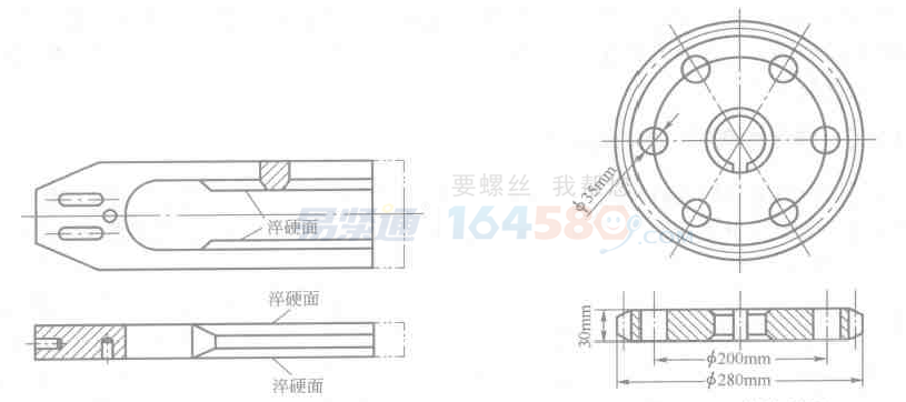 Figure 14-7 Structure of the car brace Figure 14-8 Schematic diagram of the gear
Plant Growth Light,Plant Growing Lamp,Phyto Lamp,Plant Light
SHENZHEN LITEHOME OPTOELECTRONIC TECHNOLOGY CO., LTD. , https://www.litehomelights.com