
Zhongwang Machinery is an easy-to-use and easy-to-learn CAD professional software. In the Zhongwang mechanical CAD design software, CAD designers can easily design gears and shafts. Let's first introduce you to what gears are.
Gears, as the name suggests, are mechanical components that have teeth on the rim that continuously mesh to transmit motion and power. Gears are toothed mechanical parts that can mesh with each other. The use of gears in transmissions has long appeared. At the end of the 19th century, the principle of the incision method and the special machine tools and tools that used this principle to cut the teeth appeared one after another. With the development of production, the smoothness of the gear operation was taken seriously.
Its structure generally has gear teeth, cogging, end face, normal surface, tooth top circle, tooth root circle, base circle, and index circle.
Gear teeth: referred to as teeth, are each convex part of the gear for meshing, these convex parts are generally arranged in a radial shape, the teeth on the paired gears are in contact with each other, so that the gears can continue to mesh;
Cogging: is the space between two adjacent teeth on the gear; the end is a spur gear or a cylindrical worm, perpendicular to the plane of the gear or worm axis
Normal: refers to the plane perpendicular to the tooth line of the tooth
Tip circle: refers to the circle where the tip of the tooth is located
Tooth root circle: refers to the circle where the bottom of the groove is located
Base circle: the line that forms the involute line as a purely rolling circle
Index circle: is the reference circle for calculating the geometry of the gear in the end face.
The previous section briefly introduces some definitions of gears and some of its structural classifications, as well as the interpretation of its classification nouns. Next, let's look at how to design the gear parts we need in Zhongwang Mechanical CAD software.
The steps are as follows:
After opening the Zhongwang mechanical CAD software, enter the command GEAR or click the menu to select 'Gear Design' under Mechanical Drawing to bring up the gear design dialog box, as shown in the following figure (Figure 1):
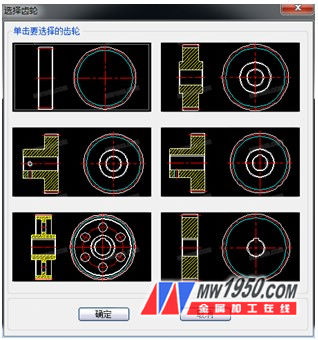
Figure 1
After calling up the dialog shown in Figure 1, at this point, we can choose different types of gear drawing methods according to the type of gear we need.
For example, if we click on the first one in the upper left corner, it will pop up a dialog box as shown in Figure 2, which includes a simple preview of the gears, the input area of ​​the geometry parameters, and the graphics control.
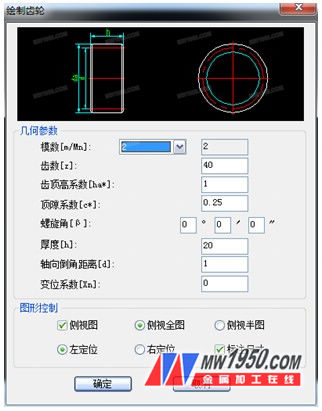
Figure II
At the same time, when drawing, we hope that it will be directly dimensioned after drawing. In this case, we only need to put a tick in the small box of “dimensioningâ€. In this case, we only need to according to what we need. For some geometric parameters, choose the graphics control method (the graphics control mainly includes the left or right positioning, and the selection of the view), click the OK below to draw the gear parts we need.
Steel Plate Punching Machine,CNC Sheet Metal Punching Machine,Steel Plate Hole Punching Machine,Metal Sheet Hole Punching Machine
Shandong EN FIN CNC Machinery Co., Ltd , https://www.shuofangcn.com